Transmitters and Receivers
Transmitters and Receivers. A Session for “ Electronics and Telecommunications ” A Fairfield University E-Course Powered by LearnLinc. Module: Communication Systems (in two parts). Texts: “Understanding Telephone Electronics,” Bigelow, Newnes, 1997, ISBN 0-7506-9944 References:
Share Presentation
Embed Code
Link
Download Presentation
- signal
- super heterodyne
- fm signal
- fm radio
- amplified signal interact
- fm receiver facts 2

conard + Follow
Download Presentation
Transmitters and Receivers
An Image/Link below is provided (as is) to download presentation Download Policy: Content on the Website is provided to you AS IS for your information and personal use and may not be sold / licensed / shared on other websites without getting consent from its author. Content is provided to you AS IS for your information and personal use only. Download presentation by click this link. While downloading, if for some reason you are not able to download a presentation, the publisher may have deleted the file from their server. During download, if you can't get a presentation, the file might be deleted by the publisher.
Presentation Transcript
- Transmitters and Receivers A Session for“Electronics and Telecommunications”A Fairfield University E-CoursePowered by LearnLinc Broadcast Systems
- Module: Communication Systems(in two parts) • Texts: • “Understanding Telephone Electronics,” Bigelow, Newnes, 1997, ISBN 0-7506-9944 • References: • Electronics Tutorial (Thanks to Alex Pounds) • Electronics Tutorial (Thanks to Mark Sokos) • Part 11 – Broadcast Systems • 5 on-line sessions plus one lab • Part 12 – Transmission & Communications • 5 on-line sessions plus one lab • Mastery Test part 6 follows this Module Broadcast Systems
- Section 11: Broadcast Systems • Frequency Division Multiplexing • AM • Modulation • Demodulation (The Envelope Detector) • FM • Modulation • Demodulation (The Phase-Locked-Loop) • Super Heterodyne Receivers • Television • Sampling Broadcast Systems
- Section 12: Transmission and Networks • Transmission Lines • Twisted pair • Coaxial Cable • Optical Fiber • Microwave Systems • Satellite Links • Telephone Systems • Local Area Networks • Cellular Phone Systems Broadcast Systems
- Section 11 Schedule Broadcast Systems
- Frequency Division Multiplexing • Here the Bandwidth of the Transmission medium is divided into “Channels” each with enough bandwidth to carry the desired information • All Channels are separated by an narrow, unused space in the spectrum called a “Guard Band” • AM Radio: The RF spectrum from 535 kHz to 1605 kHz is divided into overlapping 20 kHz channels (none overlap in a region) • FM Radio: the RF spectrum from 88 MHz to 108 MHz is divided into 200 kHz channels (double-width for stereo) • Broadcast TV: The RF Spectrum from 52 MHz to 88 MHz, 174 MHz to 216 MHz, and 470 MHz to 806 MHz is divided into 6 MHZ channels Broadcast Systems
- AM Facts • AM audio has a maximum frequency of less than 10 kHz • An AM radio channel needs ~18 kHz bandwidth • Two sidebands • Upper from fc+fmin to fc+fmax (fc+fm simple tone) • Lower from fc-fmin to fc-fmax (fc-fm simple tone) • channel spacing in each geographical region is 20 kHz or more • The AM Radio band is from 535 kHz to 1605 kHz • Carrier amplitude varies in proportion to the audio signal • AM transmitters average about 70% modulation • avoid over modulation • The carrier amplitude cannot go to zero or the spectrum gets very broad and interferes with other channels Broadcast Systems
- AM Demodulation • Two methods for AM demodulation • Mixing (multiplying by) a reproduced carrier wave • Requires locally generating a sine wave at the same frequency and in phase with the signal. • Then pass the result through a low-pass filter to get the audio • Envelope Detection (used in almost all AM receivers) • Use a diode and a RC filter to “follow” the envelope of the AM signal (which is the audio) Broadcast Systems
- FM Facts • Carrier Frequency varies in proportion to the audio signal • FM audio has a maximum frequency of less than 15 kHz • An FM radio channel needs extra bandwidth • Monaural: 200 KHz • Stereo: 400 KHz • The FM Radio band is from 88 MHz to 108 MHz(in the middle of the VHF TV Band, between channels 6 and 7) • Broadcast FM transmitters are limited to 75 KHZ maximum deviation • The FM Modulation Index is the ratio k = f / fm • Narrow Band FM (k < 1) BW approaches AM • Wide Band FM (k >1, broadcast FM is Wide-Band) has good noise immunity • FM Demodulators include: • Limiters followed by one of: Ratio Detector, Discriminator, or Zero Counter • Phase-Locked-Loop PLL (VCO, Phase Detector, Loop Filter) Broadcast Systems
- Demodulating FM • Limiter • An FM signal has no Amplitude variation(any that is there is either from noise or interference) • Amplify the signal and put it through a Limiter (Clipper – creates an almost square wave)to remove any AM • Filter out the created harmonics (odd multiples of the carrier in the square wave) to get back a clean FM Modulated Sine Wave • Detector • Use the slope of a filter to create AM that is proportional to the FM and use an envelope detector (Ratio Detector, Discriminator) • Count zero crossings per second • Use a Phase-Locked-Loop (PLL) to track the time-varying carrier Broadcast Systems
- The Phase-Locked-Loop • A PLL has three primary components • Phase Comparator: outputs a voltage proportional to the phase difference between two sine waves • VCO (Voltage-Controlled-Oscillator): A sine wave generator whose frequency increases (or decreases) when an input voltage increases (or decreases … zero input fc) • Low-Pass (loop) Filter : Lets DC and Audio through but filters out any high frequency components • The PLL locks onto the carrier and tracks the frequency variation. The voltage into the VCO is the original audio Broadcast Systems
- RF Transmitters • High-Level: Directly modulates the RF high power output stage with the audio. The information signal and the carrier sine wave are mixed after the carrier is amplified • Low-Level: Uses a “Linear Amplifier” stage after modulation to produce the required RF output power level. The information signal and the carrier sine wave are mixed before the carrier is amplified Broadcast Systems
- Transmitter Subsystems • Oscillator: Produces a sine wave at the carrier frequency • Buffer Amplifier: Increases the RF power level and isolates the oscillator from being affected by the modulator • Modulator: produces either an AM or FM signal centered at the carrier frequency. • The AM modulator is sometimes called mixing (the two signal interact or mix in a non-linear component to create sum and difference frequency signals) • FM is often done by directly modulating the Oscillator (a VCO) • Linear Amplifier: Used in a low-level modulated transmitter to amplify the modulated carrier to the desired power level Broadcast Systems
- AM Super Heterodyne Receiver • The original carrier is “Mixed” with a local oscillator that is offset in frequency by a fixed amount (the Intermediate Frequency or IF). • This produces a copy of the original spectrum centered at the IF frequency where it is filtered and amplified. Broadcast Systems
- AM Receiver Facts • RF Amplifier • Provides high voltage gain • “Tuned” to only amplify the desired RF signal and reduce the strength of other signals • Local Oscillator • Frequency is adjusted to be 455 kHz above (the “super” in super heterodyne) the desired signal’s carrier frequency • Mixer • The Local Oscillator and amplified signal interact or mix in a non-linear component to create sum and difference frequency signals • Since the L.O. frequency is higher than the carrier by 455 kHz, the difference signal is centered at the 455 kHz IF frequency • IF: Amplifies and selectively filters the difference AM signal (now centered at 455 kHz) • Envelope Detector: Recovers the original audio from the AM signal • Audio Amplifier: provides audio power to the speaker Broadcast Systems
- FM Super Heterodyne Receiver Broadcast Systems
- FM Receiver Facts • RF Section • Amplifier that provides high voltage gain • “Tuned” to amplify the FM Band and reduce the strength of other signals • Local Oscillator • Frequency is adjusted to be 10.7 MHz above the desired signal’s carrier frequency • Mixer • The Local Oscillator and amplified signal interact (mix) in a non-linear component (often a diode) to create sum and difference frequency signals • Since the L.O. frequency is higher than the carrier by 10.7 MHz , the difference signal is centered at the 10.7 MHz IF frequency • IF Amplifier: selectively filters and amplifies the difference FM signal (now centered at 10.7 MHz) • Limiter: Reduces any residual AM on the IF signal by “clipping” it • Discriminator: Recovers the original audio from the FM signal Broadcast Systems
- FM Receiver Facts 2 • De-Emphasis: Reduces the higher frequency audio components (they were boosted at the transmitter) for accurate reproduction.(this reduces the FM hiss) • AGC: Automatic Gain Control • Used in most radio and TV receivers to avoid overloading theamplifiers in the presence of a strong signal and to maintainmore uniform audio volume from station to station • AFC: Automatic Frequency Control (not shown) • Used in FM receivers to lock in to the desired signal’s carrier frequency. • The DC voltage from the FM Detector is fed back to the local oscillator to “pull” it back to the nearest signal Broadcast Systems
- Section 11 Schedule Broadcast Systems

Transmitters Receivers and Speed Controllers
Transmitters Receivers and Speed Controllers Jeff Mori Mechatronics Instructor Eastern Westmoreland CTC Spektrum DX6i I cant find my Aileron ? Remember this controller is primarily designed to be used as an airplane and helicopter controller.
652 views • 22 slides
Architectures and RF System Design Issues for Integrated Receivers and Transmitters in 3rd Generation Wireless Handsets
10/26/01. Walid Y. Ali-Ahmad. 2. TALK OUTLINE. Introduction: Example of present level of integration in an RF chipset for CDMA cellular radioReceiver ArchitecturesHeterodyne ReceiverImage-Reject ReceiverDirect-Conversion ReceiverLow-IF ReceiverTransmitter ArchitecturesIF-Modulation / Up-conversion TransmitterDirect-Modulation TransmitterOffset-PLL TransmitterSummary.
607 views • 26 slides
RF Transmitters
RF Transmitters. Architectures for Integration and Multi-Standard Operation. Terry Yao ECE 1352. Outline. Motivation Transmitter Architectures Current Trends in Integration State-of-the-Art Examples (3) Direct Conversion 2-Stage Future Challenges References. Motivation.
304 views • 15 slides
CHEMICAL TRANSMITTERS
CHEMICAL TRANSMITTERS. DEFINITION : it is the substance which transmits the nerve impulse from pre - synaptic to post - synaptic membrane . MECHANISM : Arrival of nerve impulse to Pre-synaptic membrane → causes Ca+ uptake by acetyl choline vesicles
604 views • 27 slides
Chelmsford Amateur Radio Society Foundation Course Transmitters & Receivers
Chelmsford Amateur Radio Society Foundation Course Transmitters & Receivers. Tuned Circuits. Radios depend on the concept of tuned circuits. Tuned circuits are built from combinations of Inductors and Capacitors which have a self-resonant frequency.
308 views • 10 slides
Transmitters Receivers and Speed Controllers
Transmitters Receivers and Speed Controllers. Jeff Mori Mechatronics Instructor Eastern Westmoreland CTC. Spektrum DX6i. I cant find my Aileron ?. Remember this controller is primarily designed to be used as an airplane and helicopter controller.
368 views • 22 slides

RECEIVERS
RECEIVERS. Presented By :- Er . Srishtee Chaudhary Lecturer E.C.E GPCG,Patiala. REVIEW ( Last Lecture ). TRF Receiver TRF Receiver drawbacks Instability Variation in BW Poor selectivity Super-heterodyne Receivers Receiver Characteristics Selectivity Senstivity Fidelity . CONTENTS.
1.92k views • 45 slides
Core transmitters
Core transmitters. Groups with high rates of partner exchange e.g., military, CSWs, truck drivers, young people Treating one core group infection can prevent spread to many. Core transmitters. Gonorrhoea: Treatment 100 cases in non-core groups
244 views • 4 slides
Outline: Fibre and fibercharacteristics Transmitters Modulation Receivers Passive couplers
Outline: Fibre and fibercharacteristics Transmitters Modulation Receivers Passive couplers Filters Transmission systems and optical networks. Optical fibre, characteristic. Large bandwidth (theoretical 50 THZ) Low attenuation (0,2 dB/km at 1550nm).
841 views • 65 slides
TRANSMITTERS
TRANSMITTERS a. Ionotropic (channel-linked) receptors: transmitter binds to binding site at ion channel (receptor coupled to channel) b. Metabotropic (G-protein linked) receptors: 1. Receptor activates G-protein » alpha subunit splits off » binds to ion channel.
247 views • 5 slides
Digit al Parts of Receivers and Transmitters
Digit al Parts of Receivers and Transmitters. Vilmos Rösner. Digital Parts of Receivers Digital Parts of Transmitters Special Application: Bandpass Filter. 0. f. DEM. out. Antenna output: U(t) =A(t) • exp(j •(t• ω (t)+ φ (t))). modulation-> information. Problem: receiver selectivity.
399 views • 27 slides
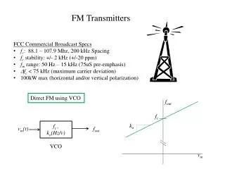
FM Transmitters
FM Transmitters. FCC Commercial Broadcast Specs f c : 88.1 – 107.9 Mhz , 200 kHz Spacing f c stability: +/- 2 kHz (+/-20 ppm) f m range: 50 Hz – 15 kHz (75uS pre-emphasis) D f c < 75 kHz (maximum carrier deviation) 100kW max (horizontal and/or vertical polarization).
372 views • 7 slides
Chelmsford Amateur Radio Society M3 Foundation Course Transmitters & Receivers
Chelmsford Amateur Radio Society M3 Foundation Course Transmitters & Receivers. Tuned Circuits. Radios depend on the concept of tuned circuits. Tuned circuits are built from combinations of Inductors and Capacitors which have a self-resonant frequency.
305 views • 10 slides
Receivers
Receivers. Receivers perform the inverse operations to transmitter Two important specifications are fundamental to all receivers: Sensitivity: the signal strength required to achieve a given signal-to-noise ratio
408 views • 18 slides
TRANSMITTERS AND RECEIVERS
TRANSMITTERS AND RECEIVERS. Frequency Modulation (FM) Receiver. Frequency Modulation (FM) Receiver. FREQUENCY MODULATION (FM) RECEIVER. Superheterodyne Receiver. Heterodyning. The word heterodyne is derived from the Greek roots hetero- "different", and -dyne "power".
570 views • 19 slides
CHEMICAL TRANSMITTERS
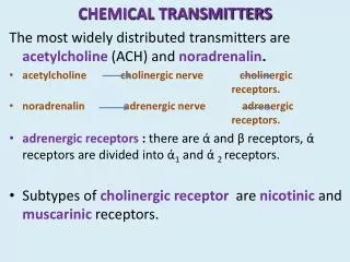
CHEMICAL TRANSMITTERS. The most widely distributed transmitters are acetylcholine (ACH) and noradrenalin . acetylcholine cholinergic nerve cholinergic receptors.
289 views • 6 slides
Receivers
6. Receivers. Receiver Characteristics: Sensitivity and Selectivity. Sensitivity Minimum input signal (voltage) required to produce specified output. Noise floor Input noise. Selectivity Extent to which receiver capable of differentiating between desired signal and other frequencies.
407 views • 25 slides
Chapter4 Transmitters and Receivers Generalized Transmitters AM PM Generation
Chapter4 Transmitters and Receivers Generalized Transmitters AM PM Generation Inphase and Quadrature Generation Superheterodyne Receiver Frequency Division Multiplexing. Huseyin Bilgekul Eeng360 Communication Systems I Department of Electrical and Electronic Engineering
420 views • 20 slides

Are Women more Efficient Transmitters and, or Receivers of Literacy and Education Externalities?
Are Women more Efficient Transmitters and, or Receivers of Literacy and Education Externalities?. Richard Palmer-Jones School of Development Studies, University of East Anglia, Workshop on Life Course, Well-being and Public Policy, 9-10/11/06.
274 views • 15 slides
